433MHz 1527 Code Tranceiver
Outline
This project was designed to fulfill two main functions, to emulate a number of 433MHz keypads and discreet 433MHz buttons, and to intercept these codes when transmitted, so it acts as both a transmitter and receiver. This unit only handles 1527 RF codes. These devices are typically used for remote control of power outlets, doorbell buttons, garage door openers, and even smoke detectors.
The unit can function as a development tool, and as a replacement for existing keypads and other hardware.
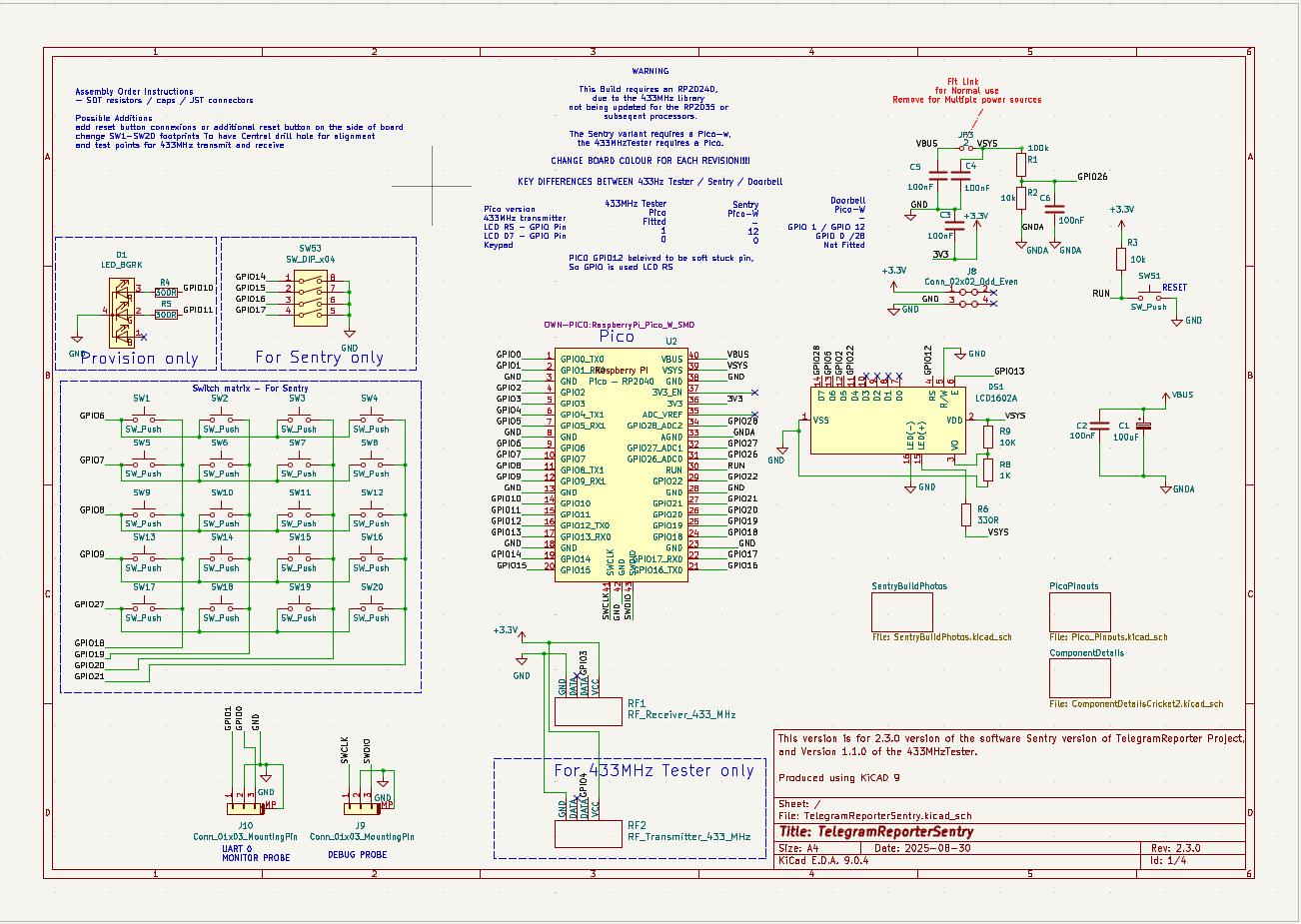
The project was designed to reuse elements of the Telegram Reporter project as far as is practical, this included the schematic and PCB design, and also the software.
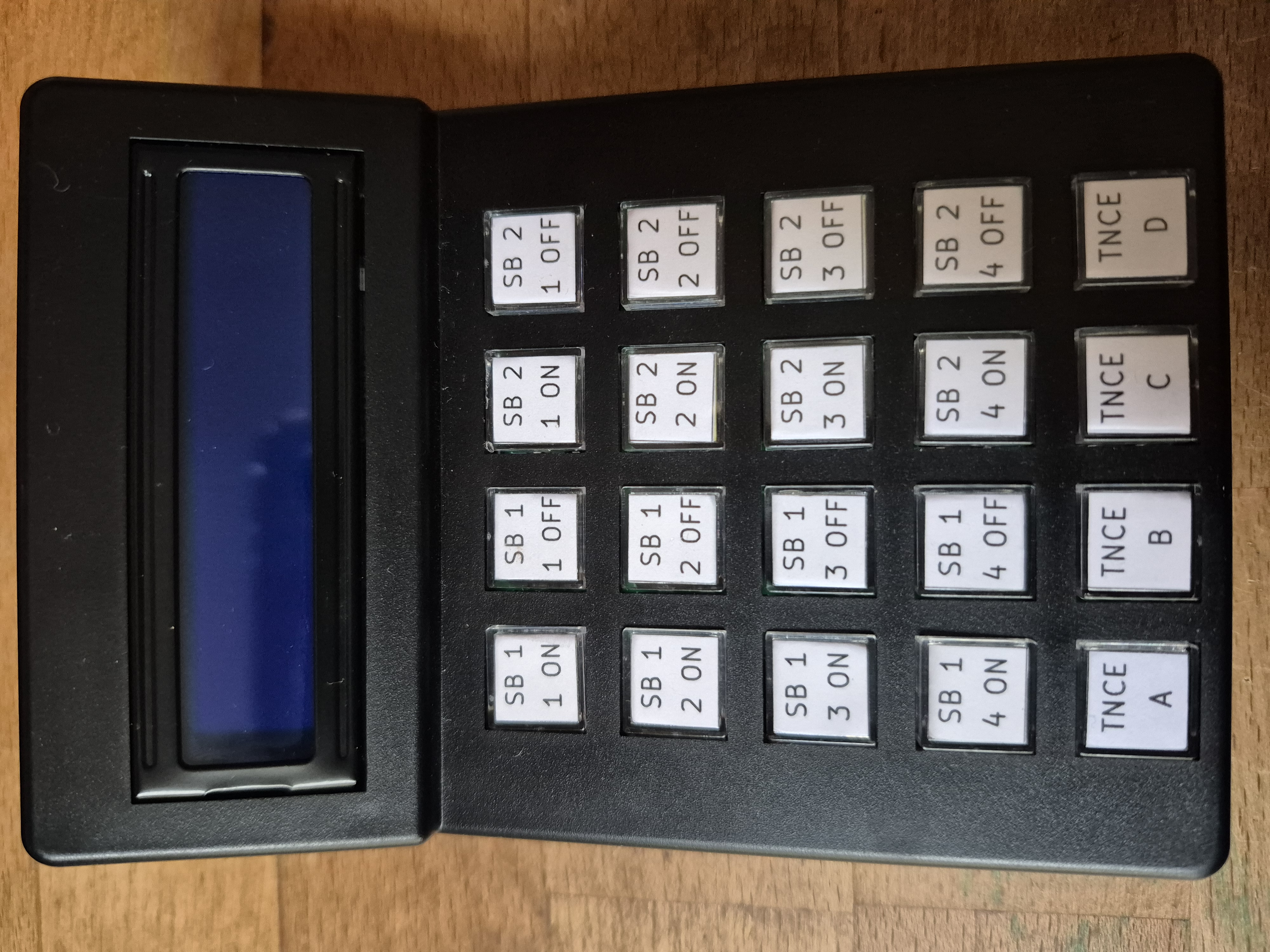
The project fits in the same calculator housing as the Telegram reporter, this is an AliExpress calculator kit, which provides the housing, display,and the buttons.
Design Notes
The software uses the 1527 remote control library xxxxx It uses the same display and keyboard handlers used in the Telegram Reporter Sentry.
Uses much of the calculator kit.
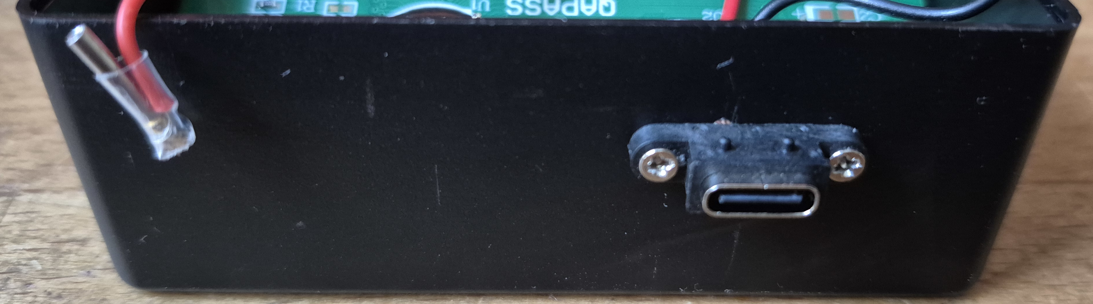
The USB 3 external connector is not ideal, but has been selected because it is small, reasonably tidy and does not require any slots or similar holes to be made in the case (which normally turn out to be ugly).
Key labels are made using an inkjet print, the design is held a KiCAD PCB file.
Images
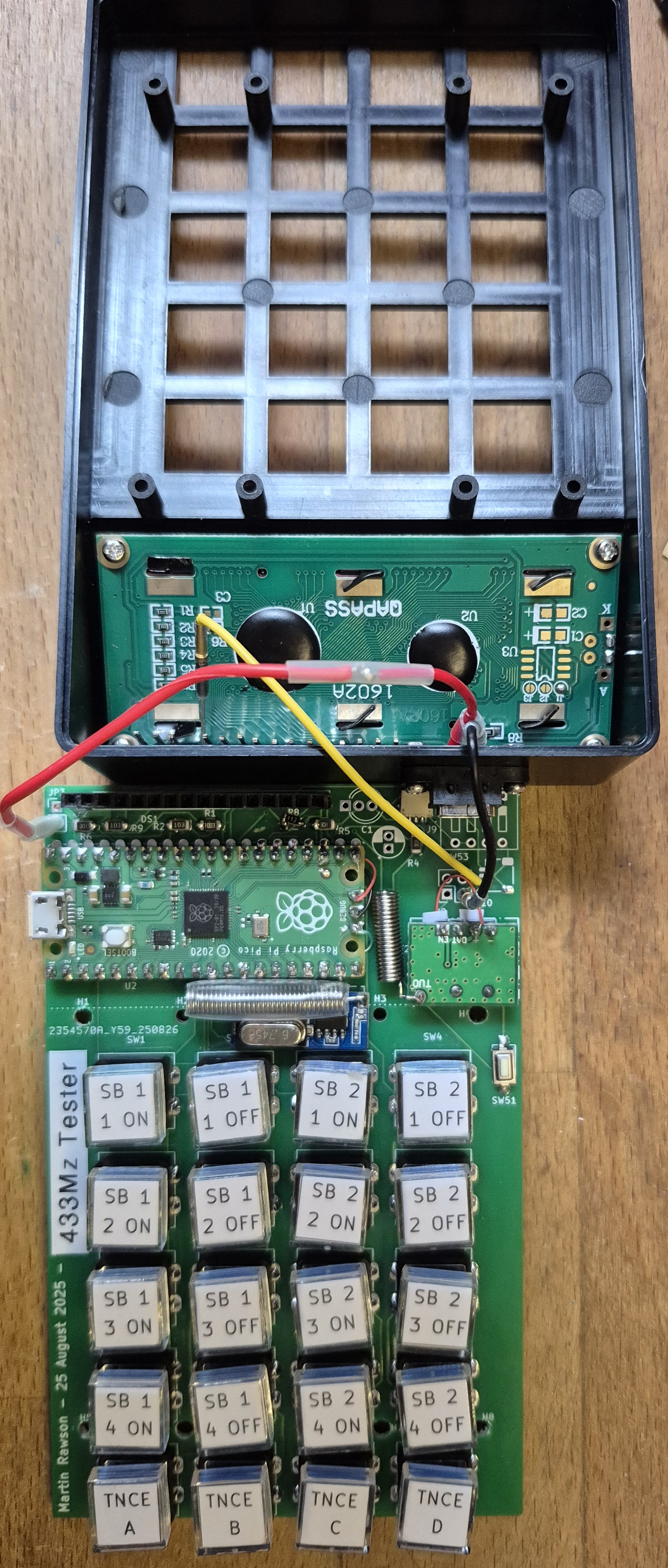
PCB
The PCB is designed fit the case as replacement for the calculator PCB, as space was available it is a larger PCB. This allows for the Pico to but up against the edge of the case. The PCB was almost entirely routed usin the xxx KiCAD compatible router.
Build Notes
Aero Pins are used to connect the power from the USB connector to the keypad board, these are cut back, because clearance is very limited between the 1602A display and the keypad board. The Aero Pins mate with Vero Pins on the PCB.
The yellow wire in the photo is a repair, the Pico 2040 chip appears to have a problem with the D12 pin, as this is soldered in place, and would be a problem to replace, I decided to reroute the signal via D1, this required the hardware link and a change to the software. This is documented in the software and the KiCAD drawings.
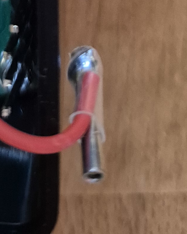
Heatshink sleve is used to cover power and other connector pins, and the two Antennas, this is to avoid shorting.
The 1602A display connector needs to be bent to fit the case, this is best done with a peice of vero board. Also the DIL pins soldered onto the 1602A display need to be trimmed back or the calculator case will not close.
Operation Notes
Four modes of operation are provided, selected by keys A-D after power up. A) Keypad emulator (transmitter) B) Receiver (shows text for keys received e.g. SB1 BTN 4 ON C) Transceiver D) Receiver (shows codes received) to be implemented!!
Applicable Links
Todo: show calculator kit sites https://www.aliexpress.com/item/1005006237361881.html
–